Control Systems
IB Syllabus: A1.3.6 – Control system components, A1.3.7 – Control systems in real-world applications
HL Only – This entire page covers content assessed at HL level only.
Key Concepts
What is a Control System? (A1.3.6)
A control system is a system that manages, commands, directs, or regulates the behaviour of other systems or processes. Control systems are found everywhere – from household thermostats that maintain comfortable room temperatures to autonomous vehicles that navigate complex traffic environments.
At its core, every control system follows the same pattern:
- Sensors measure something in the physical world
- A controller processes the sensor data and makes a decision
- Actuators carry out a physical action based on the controller’s decision
Control systems are a central HL exam topic. You need to be able to describe the components (A1.3.6) and explain how they work together in real-world applications (A1.3.7). Exam questions often ask you to identify sensors, actuators, and the controller for a given scenario, and to determine whether the system is open-loop or closed-loop.
Watch: Video Resources
What open-loop control systems are and how they work without feedback - simple examples like a toaster.

How closed-loop (feedback) control systems use sensor data to self-correct - thermostats, cruise control.

Breaking down a feedback loop: sensor, controller, actuator, and plant - with real-world examples.
Control System Components (A1.3.6)
Sensors
Sensors are devices that detect and measure physical quantities in the environment – such as temperature, light, pressure, motion, sound, or proximity – and convert them into electrical signals that a controller can process.
Key sensor properties:
- Accuracy: how close the reading is to the true value
- Range: the minimum and maximum values the sensor can measure
- Resolution: the smallest change the sensor can detect
| Sensor Type | Measures | Example Use |
|---|---|---|
| Temperature | Heat | Thermostat, oven, server room |
| Motion/PIR | Movement | Security alarm, automatic doors |
| Pressure | Force per area | Tyre pressure, weather station, washing machine load |
| Light/Optical | Light intensity | Street lights, camera exposure |
| Proximity/Range | Distance to objects | Parking sensors, phone screen off, robotics |
| Sound/Acoustic | Audio level | Voice assistants, noise monitoring |
| Accelerometer | Acceleration | Smartphone orientation, airbag deployment |
| Infrared | Heat radiation | Night vision, thermal imaging, remote controls |
| Ultrasonic | Distance via sound waves | Obstacle detection, parking sensors |
| Inductive loop | Metal/vehicle presence | Traffic light vehicle detection |
| Moisture/Humidity | Water content | Greenhouse irrigation, weather stations |
| Speed | Rotational/linear velocity | Vehicle speedometer, washing machine drum |
| Vibration | Mechanical oscillation | Washing machine balance, industrial monitoring |
| Load/Weight | Mass | Washing machine load detection, industrial scales |
Transducers
A transducer is any device that converts energy from one form to another.
- A sensor is an input transducer – it converts a physical quantity (e.g., temperature, sound, light) into an electrical signal
- An actuator can be an output transducer – it converts an electrical signal into a physical action (e.g., movement, sound, heat)
Common transducer examples:
- Microphone: sound energy –> electrical signal (input transducer)
- Speaker: electrical signal –> sound energy (output transducer)
- Thermistor: temperature change –> resistance change (input transducer)
- Motor: electrical signal –> rotational movement (output transducer)
All sensors are transducers (they convert physical quantities to electrical signals), but not all transducers are sensors – some are output transducers (actuators).
Controllers (Microprocessors)
The controller is the “brain” of the control system. It is typically a microprocessor or microcontroller that:
- Receives input from sensors (via an ADC – Analog to Digital Converter)
- Processes the data according to a control algorithm stored in ROM
- Sends output signals to actuators (via a DAC – Digital to Analog Converter)
Advantages of microprocessor controllers:
- Fast – can process thousands of readings per second
- Tireless – operate 24/7 without fatigue or loss of concentration
- Consistent – always follow the same algorithm; no human error
- Can operate in harsh environments – extreme temperatures, toxic atmospheres, high radiation
Limitations:
- Can only respond to situations they are programmed for – cannot improvise or handle unexpected scenarios outside their algorithm
- Require careful programming – a bug in the control algorithm can cause system failure
Actuators
Actuators are devices that produce a physical action based on the controller’s output signal. They convert electrical signals from the controller into physical movement, heat, light, or sound.
Common actuator examples:
- Motors – produce rotational or linear movement (e.g., steering, conveyor belts)
- Valves – open or close to control fluid/gas flow (e.g., water irrigation, heating)
- Heaters – produce heat (e.g., oven, room heating)
- Lights – produce illumination (e.g., indicator lights, display screens)
- Speakers – produce sound (e.g., alarm sirens, voice output)
- Relays – electrically controlled switches that turn high-power devices on/off
ADC and DAC
Most real-world quantities (temperature, light, sound) are analog – they vary continuously. Computers, however, work with digital data (discrete binary values). Two converters bridge this gap:
- ADC (Analog to Digital Converter): converts the analog electrical signal from a sensor into digital data that the controller can process. For example, a temperature sensor outputs a voltage that varies smoothly with temperature – the ADC converts this to a number the microprocessor can work with.
- DAC (Digital to Analog Converter): converts the digital output from the controller into an analog signal that actuators can use. For example, the controller calculates that the motor should run at 75% speed – the DAC converts this to the appropriate voltage level.
Control System Pipeline
The complete flow of data through a control system follows this path:
flowchart LR
    P([Physical quantity]) --> S[Sensor]
    S --> ADC[ADC<br/><em>analog -> digital</em>]
    ADC --> C[Controller<br/><em>decision</em>]
    C --> DAC[DAC<br/><em>digital -> analog</em>]
    DAC --> A[Actuator]
    A --> PA([Physical action])
    classDef io fill:#fff,stroke:#888,stroke-dasharray:3 3,color:#333
    classDef ctrl fill:#3DAA8A20,stroke:#3DAA8A,color:#1f5d4a
    class P,PA io
    class C ctrl
The pipeline can be summarised as: Physical world –> Sensor –> ADC –> Controller –> DAC –> Actuator –> Physical world. Exam questions often ask you to trace through this pipeline for a specific application.
Open-Loop vs Closed-Loop Systems (A1.3.7)
The most important distinction in control systems is whether or not the system uses feedback.
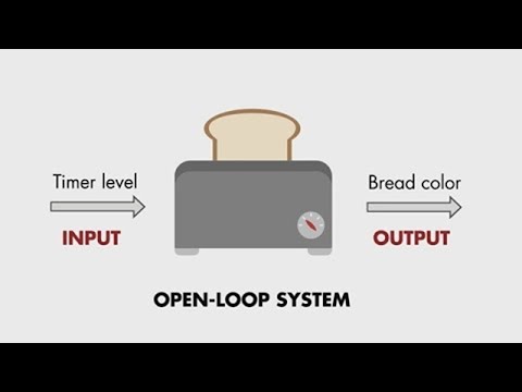
Open-Loop System
An open-loop control system has no feedback – the output is not measured or compared to the desired value. The system runs a fixed sequence of actions regardless of the actual result.
Characteristics:
- Runs a pre-set sequence or operates for a fixed time
- Does not measure its own output
- Cannot self-correct – if something goes wrong, the system does not know
- Simpler and cheaper to design and build
- Less accurate – cannot compensate for disturbances
Example: A basic toaster – heats bread for a set time (e.g., 3 minutes) regardless of how brown the bread actually gets. If the bread is already warm or the element is weaker than usual, the toaster does not adjust.
Example: A washing machine – follows a fixed cycle (fill –> wash –> rinse –> spin) regardless of how clean the clothes are. The user selects a program, and the machine runs that exact sequence from start to finish.
Closed-Loop System
A closed-loop control system has feedback – the output is continuously measured by a sensor and compared to the desired value (the setpoint). The controller adjusts its actions based on the difference (the error) between the actual output and the desired output.
Characteristics:
- Measures its own output through sensors
- Compares actual output to the setpoint (desired value)
- Calculates the error (setpoint - actual)
- Self-correcting – automatically adjusts to reduce error
- More complex and expensive to design
- More accurate and reliable – adapts to changing conditions
Example: A thermostat – the temperature sensor measures the room temperature, the controller compares it to the setpoint (e.g., 22 degrees C), and turns the heater on or off to maintain that temperature. If the room cools down, the heater turns on. If it warms up past the setpoint, the heater turns off.
Example: Cruise control – a speed sensor measures the vehicle’s current speed, the controller compares it to the target speed, and adjusts the throttle to maintain that speed. If the car goes uphill and slows down, the controller increases throttle; if it goes downhill and speeds up, the controller reduces throttle.
Closed-Loop Feedback Diagram
flowchart LR
    SP([Setpoint]) --> CMP[Comparator]
    CMP --> CTRL[Controller]
    CTRL --> ACT[Actuator]
    ACT --> PROC[Process]
    PROC --> OUT([Output])
    PROC -.->|measured by| SNS[Sensor]
    SNS -.->|feedback| CMP
    classDef io fill:#fff,stroke:#888,stroke-dasharray:3 3,color:#333
    class SP,OUT io
The comparator calculates: error = setpoint - actual output. The controller then uses this error value to decide what action to take. This feedback loop runs continuously – the sensor measures the output, the controller compares it against the pre-set stored value, calculates the adjustment needed, and sends a signal to the actuator, repeating this cycle indefinitely. The continuous nature of this loop is what makes closed-loop systems self-correcting.
Comparison Table
| Feature | Open-Loop | Closed-Loop |
|---|---|---|
| Feedback | No | Yes |
| Self-correcting | No | Yes |
| Complexity | Simple | More complex |
| Cost | Lower | Higher |
| Accuracy | Lower (no error correction) | Higher (adjusts based on feedback) |
| Reliability | Less (cannot respond to disturbances) | More (adapts to changes) |
| Response to disturbance | None | Adjusts automatically |
| Example | Toaster, washing machine | Thermostat, cruise control |
A common exam mistake is confusing open-loop and closed-loop. The key distinction is feedback: if the system measures its own output and adjusts, it is closed-loop. If it runs a fixed sequence regardless, it is open-loop.
Real-World Applications (A1.3.7)
Exam questions frequently ask you to describe how a control system is used in a specific real-world context. For each application, you should be able to identify the sensors, controller, actuators, and whether it is open-loop or closed-loop.
1. Smart Thermostat (Closed-Loop)
- Sensors: temperature sensor (measures room temperature)
- Controller: microprocessor (compares actual temperature to setpoint)
- Actuators: heater (turns on when too cold), air conditioning (turns on when too hot)
- Feedback: temperature sensor continuously feeds back the current room temperature
- The system maintains a stable temperature by cycling the heater/AC on and off
2. Autonomous Vehicle (Closed-Loop)
- Sensors: LIDAR (distance mapping), cameras (lane detection, object recognition), GPS (location), accelerometer (speed/direction), ultrasonic sensors (parking)
- Controller: onboard computer running AI algorithms
- Actuators: steering motor, brakes, throttle, indicator lights
- Feedback: all sensors continuously feed data back to the controller, which makes real-time driving decisions
3. Washing Machine (Open-Loop)
- Sensors: user input (program selection dial or buttons)
- Controller: timer/microcontroller (follows a fixed program sequence)
- Actuators: water inlet valve, drain valve, motor (drum rotation), heater
- Feedback: none – the machine follows the same cycle regardless of cleanliness
- Note: some modern machines may use a turbidity sensor (water clarity) to adjust rinse cycles – making them partially closed-loop
4. Traffic Light System (Can Be Either)
Traffic lights can be implemented as either open-loop or closed-loop systems:
Fixed-time traffic light (open-loop):
- Do NOT take the environment into account – simply change colour after a pre-programmed amount of time
- Every two minutes the lights cycle regardless of how many cars are waiting
- No sensors measure traffic flow
Dynamic control traffic light (closed-loop):
- Uses sensors (inductive loops in the road, cameras, or buttons) to detect vehicles or pedestrians
- The controller processes sensor input and adjusts the timing:
- If no cars are waiting on the secondary road, the main road stays green
- If a pedestrian presses the button, the main road turns red and the pedestrian light turns green
- If a vehicle approaches from the secondary road, the system adjusts the cycle
- The output (traffic flow) affects the input (sensor readings), which affects the next output – a feedback loop
System pipeline (dynamic version):
- Sensors: buttons, motion/vehicle detectors, cameras, timer, input from control centre
- ADC converts analog signals to digital
- Controller (microprocessor): runs control algorithm to calculate the timer sequence and traffic light operation
- DAC converts digital output to analog signals
-
Actuators: change lights/sequence, sound/alerts for pedestrians
- Controller: traffic management computer
- Actuators: traffic light LEDs
5. Automatic Doors (Closed-Loop)
The step-by-step flow of an automatic door system:
- Optical/motion sensors (or a manual button) detect an approaching person
- Analog signals are sent to the ADC, which converts them into digital signals
- The digital signals are sent to the microcontroller
- The control system inside the microcontroller receives the input, processes it, and compares it with a pre-set threshold
- If the value exceeds the threshold, a command is issued as an output
- The DAC converts the controller’s output into an analog signal and sends it to the actuators
- Actuators (electric motors) produce physical motion to open/close the door
- Sensors: motion sensor or pressure mat (detects approaching person)
- Controller: microprocessor (activates door when person detected, closes after delay)
- Actuators: electric motor (opens/closes the door via pulley system)
- Feedback: sensor continuously monitors whether someone is in the doorway; door stays open while person is detected
6. Security Alarm System (Closed-Loop)
- Sensors: PIR motion sensors, door/window contact sensors, glass break sensors
- Controller: alarm control panel (monitors all sensor zones)
- Actuators: siren/speaker, strobe light, notification to monitoring centre (via network)
- Feedback: sensors continuously report zone status; controller responds to any breach
7. Greenhouse Irrigation (Closed-Loop)
- Sensors: soil moisture sensor, temperature sensor, humidity sensor, light sensor
- Controller: microprocessor (compares soil moisture to threshold)
- Actuators: water valves (open to irrigate, close when moisture is sufficient), ventilation fans, heaters
- Feedback: soil moisture sensor continuously measures water level; watering stops when threshold is reached
8. Elevator Controller (Closed-Loop)
- Sensors: floor position sensors, weight sensor (overload detection), call buttons (each floor), door obstruction sensor
- Controller: elevator control unit (optimises travel based on call requests and current position)
- Actuators: motor (moves car up/down), door motor (opens/closes doors), display (shows floor number)
- Feedback: position sensors report current floor; controller adjusts motor direction and stopping
When describing a real-world control system in an exam, always structure your answer around the four components: sensor (what it measures), controller (what it decides), actuator (what physical action it takes), and feedback (whether and how the output is measured).
How robots use sensors, actuators, and control systems to interact with the physical world.
Enrichment: Embedded Systems
This section provides additional context. Embedded systems are mentioned in A1.3.4 (polling and interrupts) as a real-world scenario but are not a standalone assessed topic.
An embedded system is a microprocessor built into a larger device to perform a specific, dedicated task. Unlike a general-purpose computer that can run any software, an embedded system is designed for one fixed function and operates with minimal or no user interaction.
Key characteristics:
- Fixed functionality – programmed to perform a specific task (not a general-purpose computer)
- Built into the larger system – the user may not even be aware there is a processor inside
- Runs continuously – often operates 24/7 without user intervention
- Real-time response – many embedded systems must respond within strict time limits
Examples of embedded systems include household appliances (washing machines, microwaves), automotive systems (engine management, airbag controllers), medical devices (pacemakers, insulin pumps), and smart home devices (thermostats, security cameras). Most of the control systems described on this page use embedded microprocessors as their controllers.
Enrichment: Centralized vs Distributed Control
This section goes beyond the IB 2027 syllabus but builds understanding of how control systems are designed at scale.
When designing a control system with multiple components, a key decision is whether to use centralized or distributed control.
Centralized control uses a single central processor that manages all sensors and actuators in the system. All data flows to and from this one controller.
- Easier to synchronize actions across the whole system because one processor has a complete view of all data
- Simpler to maintain and update because there is only one controller to manage
- Provides a single point for data collection and logging
- However, the central controller is a single point of failure – if it fails, the entire system stops
- Can become a bottleneck as the system scales – one processor must handle all inputs and outputs
- Requires a reliable network connection between the central controller and all remote sensors/actuators
Distributed control uses multiple independent processors, each managing its own local sensors and actuators. The processors may communicate with each other but can also operate independently.
- No single point of failure – if one processor fails, others continue operating
- Faster local response because each processor only handles its own subsystem
- More scalable – add new subsystems by adding new controllers
- Reduced autonomy of the whole system – individual processors may make conflicting decisions
- Harder to coordinate actions that require input from multiple subsystems
- More complex to maintain because there are multiple controllers to manage and update
When evaluating centralized vs distributed control, consider both sides. Centralized offers better coordination and simpler maintenance but creates a single point of failure. Distributed offers better reliability and scalability but is harder to coordinate.
Complex Control Systems and Autonomous Agents (A1.3.7)
Complex control systems go beyond simple sensor-controller-actuator loops. They use algorithms and programs running on computers, combined with sensors and effectors (actuators), to observe their environment and take actions – creating a continuous interaction loop.
flowchart LR
AGT["<b>Computer & Program</b><br/>algorithms +<br/>sensors & effectors"]
ENV["<b>Environment</b>"]
AGT -->|action| ENV
ENV -->|observation| AGT
Examples of complex control systems include robot vacuum cleaners (sensing obstacles and mapping rooms), autonomous drones (navigating flight paths), and chess-playing robots (observing board state, computing moves).
Agents
An agent is an entity that can:
- Perceive its environment through sensors
- Act upon that environment through effectors (actuators)
- Follow algorithms supplied by an owner to achieve a desired goal
Autonomous Agents
An autonomous agent is a more advanced agent that operates on behalf of an owner with a degree of autonomy and with minimal to no interference:
- They perform actions that depend on their own “experiences” through their sensors
- They can apply different sets of pre-programmed actions in different situations and even build their own set of actions through learning algorithms
- They display artificial intelligence in that they need to “reason” according to their acquired knowledge
- The representation of knowledge is a key concept for these agents
Types of Agents
| Situated (in a physical environment) | Not Situated (virtual environment) | |
|---|---|---|
| Embodied (has a physical form) | Mobile robots (e.g., warehouse robots) | Traditional industrial robots (e.g., assembly line arms) |
| Not Embodied (software only) | Softbots (e.g., web crawlers, smart assistants) | Computer simulations (e.g., game NPCs) |
Examples of Autonomous Agents
| Example | Autonomous Agent | Larger System | Role of the Agent |
|---|---|---|---|
| Self-Driving Car | AI driving system | Urban traffic system | Senses roads, objects, and signals; makes driving decisions to improve safety and flow |
| Smart Home Assistant | Google Assistant / Alexa | Smart home ecosystem | Responds to voice commands to control lights, AC, music, etc., without human oversight |
| Warehouse Robots | Individual mobile robot units | Automated warehouse system | Moves items based on orders, communicates with other robots for efficiency |
| Agricultural Drone | Autonomous flying drone | Precision agriculture system | Scans crops, sprays fertiliser/pesticides, collects data for farming decisions |
| Game NPCs | Non-Player Characters (NPCs) | Game environment | Interact with players or other NPCs based on rules, adding depth and realism to games |
Watch: Autonomous Vehicles

Overview of the levels of autonomy in vehicles -- from foot-free to fully driverless -- and the sensor technologies that make them possible.
Exam tip: When describing an autonomous agent, explain three things: (1) what sensors it uses to perceive its environment, (2) what decisions it makes autonomously, and (3) what actuators it uses to act on those decisions.
Worked Examples
Example 1: Thermostat as a Closed-Loop System
This example traces through the feedback cycle of a thermostat set to maintain 22 degrees C.
| Step | What Happens | Component |
|---|---|---|
| 1 | User sets desired temperature to 22 degrees C | Setpoint = 22 degrees C |
| 2 | Temperature sensor reads current room temp: 18 degrees C | Sensor (input) |
| 3 | ADC converts the analog reading to digital data | ADC |
| 4 | Comparator calculates error: 22 - 18 = 4 degrees C (too cold) | Comparator |
| 5 | Controller sends signal to turn heater ON | Controller (decision) |
| 6 | DAC converts digital signal to analog for the heater relay | DAC |
| 7 | Heater turns ON, room temperature rises | Actuator (heater) |
| 8 | Room temperature reaches 22 degrees C | System output |
| 9 | Sensor reads 22 degrees C, error = 0 | Feedback (sensor measures output) |
| 10 | Controller sends signal to turn heater OFF | Controller (adjusts) |
| 11 | Room cools slightly to 21 degrees C | Disturbance (heat loss) |
| 12 | Sensor reads 21 degrees C, error = 1 degrees C | Feedback (detects change) |
| 13 | Controller turns heater ON again | Controller (self-corrects) |
This continuous cycle – measure, compare, adjust – is the hallmark of a closed-loop system. The temperature oscillates slightly around the setpoint but stays within an acceptable range.
Example 2: Traffic Light Intersection (Closed-Loop)
An intersection of a main road and a secondary road is regulated by a set of traffic lights. The secondary road is a one-way street. Pedestrian lights are also present.
How the system works:
- When a pedestrian presses the button, the traffic lights on the main road change to red (STOP), while the traffic lights on the secondary road turn red (STOP), allowing people to cross
- If no pedestrians want to cross and there is a vehicle on the secondary road, the pedestrian lights and the traffic lights on the main road turn red (STOP) and green (GO) on the secondary road
- Otherwise, every two minutes the lights cycle automatically
How the sensors work:
- A touch/weight sensor in the road or a camera detects an approaching or waiting vehicle on the secondary road
- An ADC converts the analog signal from the sensor to its digital counterpart
- The digital signal is processed by the microprocessor (controller)
- A signal is sent to the traffic lights so that the pedestrian and the main road traffic lights turn red (Stop), while the traffic lights on the secondary road turn green (Go)
The role of interrupts: A signal sent to the processor requesting immediate attention is an interrupt. For example: a vehicle approaches from the secondary road and the sensors send a signal to the microprocessor. At the same time, a pedestrian presses the button. An interrupt signal is sent to the microprocessor requesting immediate attention, changing the traffic lights on the secondary road to red (Stop) while the pedestrian lights turn green (Go).
Example 3: Washing Machine as an Open-Loop System
This example traces through a washing machine’s fixed program cycle.
| Step | What Happens | Component |
|---|---|---|
| 1 | User selects “Cotton 60 degrees C” program | Input (user selection) |
| 2 | Controller opens water inlet valve (fill for 5 minutes) | Actuator (valve) |
| 3 | Controller activates heater (heat water to 60 degrees C) | Actuator (heater) |
| 4 | Controller runs motor – drum rotates (wash for 15 minutes) | Actuator (motor) |
| 5 | Controller opens drain valve | Actuator (valve) |
| 6 | Controller fills again with clean water | Actuator (valve) |
| 7 | Controller runs motor (rinse for 10 minutes) | Actuator (motor) |
| 8 | Controller runs motor at high speed (spin for 5 minutes) | Actuator (motor) |
| 9 | Program complete – machine stops | End of fixed sequence |
Notice that at no point does the machine measure how clean the clothes are. It follows the same sequence every time regardless of the result. This is what makes it open-loop – there is no feedback from the output (cleanliness) to the controller.
A common exam trap: students sometimes argue that a washing machine is closed-loop because the heater uses a thermostat to reach 60 degrees C. While there may be an internal temperature sensor for heating water, the overall washing process is open-loop because the machine never measures the cleanliness of the clothes and adjusts accordingly.
Quick Check
Q1. What feature distinguishes a closed-loop control system from an open-loop control system?
Q2. What is the role of an ADC in a control system?
Q3. Which of the following is an example of an open-loop control system?
Q4. What is the role of an actuator in a control system?
Q5. A sensor is an example of what type of transducer?
Q6. Which of the following best describes an autonomous agent?
Q7. Which of the following is NOT an example of an autonomous agent?
Trace Exercise
Thermostat Control Cycle
A thermostat is set to maintain 20 degrees C. The heater warms the room by 2 degrees C per minute when on. The room cools by 1 degree C per minute when the heater is off. The heater turns ON when the temperature is below the setpoint and OFF when the temperature reaches or exceeds the setpoint. Initial temperature: 16 degrees C.
Fill in the missing values for each minute.
| Minute | Sensor Reading | Error (Setpoint - Actual) | Heater |
|---|---|---|---|
| 0 | 16 degrees C | degrees C | |
| 1 | degrees C | degrees C | |
| 2 | degrees C | degrees C | |
| 3 | degrees C | degrees C |
Spot the Error
A student wrote revision notes comparing open-loop and closed-loop control systems. One line contains an error. Click the line with the error, then pick the correct fix.
Pick the correct fix for line 3:
Fill in the Blanks
Label the components of a control system by filling in the correct term for each description.
Fill in the blanks to label each component of a control system:
CONTROL SYSTEM COMPONENTS
=========================
A  detects physical quantities and converts them to electrical signals.

An  converts analog sensor signals to digital data.

The  processes input data and decides on an action.

A  converts digital output to analog signals.

An  produces physical action based on the controller's output.
Predict the Output
A basic toaster heats bread for exactly 3 minutes regardless of how brown it gets. The toaster does not have a colour sensor and cannot adjust the heating time.
Is this an open-loop or closed-loop system? (Type open-loop or closed-loop)
A smart thermostat maintains room temperature at 22 degrees C. When the temperature drops to 20 degrees C, the heater turns on. When it reaches 22 degrees C, the heater turns off.
Is this an open-loop or closed-loop system? (Type open-loop or closed-loop)
Practice Exercises
Core
-
Control System Components – Name and describe the four main components of a control system (sensor, controller, actuator, transducer). For each component, give one specific real-world example and explain what it does in that context.
-
Open vs Closed – Explain the difference between open-loop and closed-loop control systems. For each type, give one example and state whether it uses feedback. Explain why the open-loop example does not need feedback and why the closed-loop example does.
-
ADC and DAC – Describe the role of an ADC and a DAC in a control system. Explain why these converters are necessary – why can the controller not work directly with the sensor’s analog signal?
Extension
- Smart Greenhouse – A smart greenhouse uses a control system to maintain ideal growing conditions. For this system:
- (a) Identify all sensors that would be needed and what each measures
- (b) Identify all actuators and what each controls
- (c) Describe the role of the controller
- (d) Explain whether this is an open-loop or closed-loop system, and justify your answer
- (e) Draw and label a feedback diagram for the temperature control component
- Open-Loop Confusion – Explain why a washing machine is considered open-loop even though modern machines may contain internal sensors (e.g., a water temperature sensor). In your answer, distinguish between the overall system behaviour and individual sub-components that may use feedback.
Challenge
- Autonomous Drone – Design a closed-loop control system for an autonomous drone that must maintain a fixed altitude of 10 metres. In your answer:
- (a) Identify all sensors needed and justify each choice
- (b) Describe the controller’s decision logic (what inputs it receives, what calculations it performs, what outputs it produces)
- (c) Identify all actuators and explain how they respond to the controller’s output
- (d) Draw and label the complete feedback loop
- (e) Explain how the system would handle a sudden gust of wind that pushes the drone upward to 12 metres
- IB-Style 6-Mark Question – Compare and contrast the use of control systems in a traditional washing machine and a modern self-driving car. In your answer, refer to:
- The sensors used in each system
- The actuators used in each system
- Whether each system uses feedback and why
- The role of the controller in each system
- Which system is open-loop and which is closed-loop, with justification
IB-Style Exam Questions (6 marks each)
-
Autonomous Vehicles – Explain the role of sensors, controllers, and actuators in the functioning of autonomous vehicles. [6 marks]
-
Traffic Signal Control – Explain how traffic signal control systems use sensors and controllers to manage traffic flow at intersections. [6 marks]
-
Home Security – Evaluate the use of control systems in home security, focusing on the types of sensors employed and their functions. [6 marks]
TOK Discussion
These TOK (Theory of Knowledge) prompts connect control systems to broader questions about knowledge, responsibility, and ethics. Discuss in pairs or small groups.
Safety and Assumptions: What assumptions about safety, humans, and computers are embedded into the design of autonomous vehicle control systems?
Responsibility and Knowledge: If an autonomous vehicle causes an accident, who is responsible: the software engineer who wrote the algorithm, the company that sold the car, the sensors that failed, or the passenger who chose to use the vehicle?
Ethics and Trade-offs: Should a control system ever be designed to make ethical decisions, such as choosing between two harmful outcomes?
Connections
- Prerequisites: OS Fundamentals – the OS manages device I/O and runs control software; understanding device management and drivers explains how sensors and actuators communicate with the controller
- Related: Polling and Interrupts – control systems use both polling (regular sensor readings at fixed intervals) and interrupts (emergency events such as a safety threshold being exceeded) for data acquisition
- Related: Scheduling – real-time control systems require predictable scheduling to ensure sensor readings and actuator responses happen within strict time deadlines
- Related: CPU Architecture – microprocessor controllers use the same fetch-decode-execute cycle as general-purpose CPUs; understanding registers and the ALU explains how the controller processes sensor data
- Forward: Applications Layer – control systems are embedded in many real-world applications including robotics, manufacturing, transport, and smart buildings (A3)